PlantUML: the missing piece in your project’s documentation | Drawing diagrams with text
Before we get started, I would like to thank Richard Den Adel who introduced Plant UML to me. Thank you, Richard!
This story is also available on YouTube, you can watch it here.

Documentation? I hope you are not afraid of this word. There are only a few developers I know who truly enjoy writing and designing this essential piece of every project.
While documentation might be loved by a few and frowned upon by others, all of you have suffered when onboarding a project you’re not familiar with, without proper documentation.
I understand, you’re a developer, you’re supposed to be writing code, to be pressing down all these keys in order to listen to that pleasing sound of your mechanical keyboard.
Clicking, dragging, swiping, that’s not really your thing… You don’t want to spend hours playing of drawing diagrams with the most variety of tools available for that matter.
More than that, even if you draw a diagram, you don’t want to memorize the rules of UML, different types of shapes, arrows, lines… Your drawing is pretty understandable, if you had scribbled it on a napkin while drinking a beer at your local bar, the result would’ve probably been the same.
I know, I know, I don’t like that either. (Am I lying? I love writing, that’s why I write here in the first place). But wait, I don’t like drawing, that’s for sure… And that’s why I love PlantUML!
I love PlantUML because it’s fast, it’s pleasing, and it’s all I love doing but doing something different. I can draw my diagrams without swiping, dragging, scratching, or clicking… I can code and see results and I can break it if I don’t follow the proper syntax. That’s lovely in my opinion.
What is PlantUML
In a nutshell, Plant UML is a component that allows you to write UML diagrams and other non-UML diagrams in a powerful and quick way.
You can check their documentation at: https://plantuml.com
What is UML?
UML, or Unified Modeling Language, is a language intended to provide a standard way to visualize the design of a system.
It was created to define a common modeling language for the architecture, design, and implementation of complex software systems both structurally and behaviorally.
UML diagrams are categorized under two branches: Structural and Behavioral:

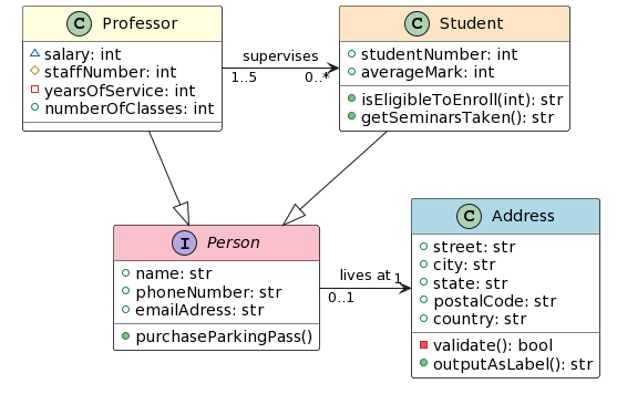
Example of a Class Diagram following UML

Have you seen a diagram like this before? This is a UML Class Diagram. Now imagine drawing it… Dragging and dropping all these shapes, resizing, copying and pasting, pulling arrows, rearranging them, rearranging everything because they don’t fit in the canvas anymore…
Forget about it, that’s how you would draw this diagram using PlantUML:
@startumlinterface Person #line:black;header:pink;back:white {
  +name: str
  +phoneNumber: str
  +emailAdress: str
  +purchaseParkingPass()
}class Address #line:black;header:lightblue;back:white {
  +street: str
  +city: str
  +state: str
  +postalCode: str
  +country: str
  -validate(): bool
  +outputAsLabel(): str
}class Student #line:black;header:bisque;back:white {
  +studentNumber: int
  +averageMark: int
  +isEligibleToEnroll(int): str
  +getSeminarsTaken(): str
}class Professor #line:black;header:lightyellow;back:white {
  ~salary: int
  #staffNumber: int
  -yearsOfService: int
  +numberOfClasses: int
}Person "0..1" -> "1" Address : lives at
Professor --|> Person
Student --|> Person
Professor "1..5" -> "0..*" Student : supervises@enduml
And this would be the result you would get:
Other Types of Diagrams
Class Diagram
A class diagram is the most commonly used UML diagram that maps the structure of a system’s classes, attributes, functions, and relations.
This is the one you saw in the example above.
Sequence Diagram
A sequence diagram is a type of interaction diagram because it describes how — and in what order — a group of objects works together. These diagrams are used by software developers and business professionals to understand requirements for a new system or to document an existing process.
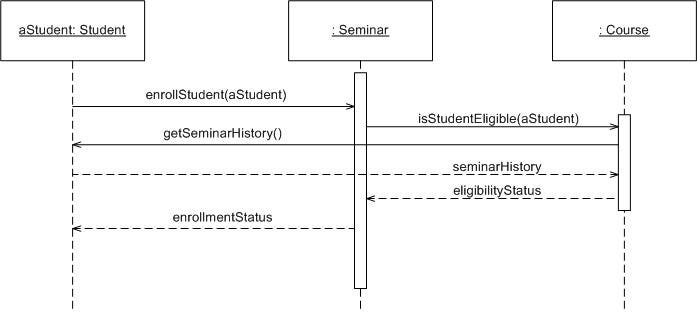
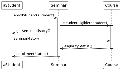
Let’s see how we can remake this diagram using PlantUML
@startumlparticipant aStudent #white
participant Seminar #white
participant Course #whiteaStudent -> Seminar: enrollStudent(aStudent)
activate SeminarSeminar -> Course: isStudentEligible(aStudent)
activate CourseCourse -> aStudent: getSeminarHistory()
aStudent --> Course: seminarHistoryCourse --> Seminar: eligibilityStatus()
deactivate CourseSeminar --> aStudent: enrollmentStatus()
deactivate Seminar@enduml
The code above will result in:
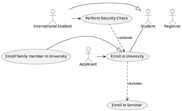
Use Case Diagram
Use-case diagrams describe the high-level functions and scope of a system. These diagrams also identify the interactions between the system and its actors. The use cases and actors in use-case diagrams describe what the system does and how the actors use it, but not how the system operates internally.
Let’s try to recreate it using PlantUML:
@startuml:Student:--(Enroll in University)
:Applicant:->(Enroll in University):International Student:-|>:Student:
:International Student:->(Perform Security Check)(Enroll family member in University) -|> (Enroll in University)
(Enroll in University) ...> (Enroll In Seminar) : <<include>>
(Perform Security Check) ..> (Enroll in University) : <<extend>>@enduml
The code above will result in:
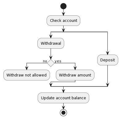
Activity Diagram
Activity diagrams are graphical representations of workflows of stepwise activities and actions with support for choice, iteration, and concurrency. It is essentially an advanced version of a flow chart that models the flow from one activity to another activity.
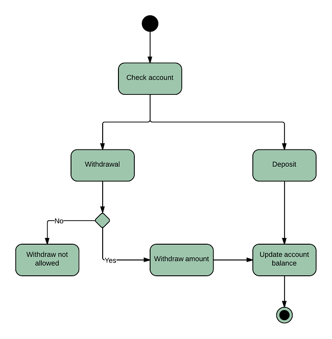
Let’s recreate it in PlantUML:
@startumlstart
:Check account;
split
:Withdrawal;if () then (no)
  :Withdraw not allowed;
  detach
else (yes)
  :Withdraw amount;
endifsplit again
  :Deposit;
end split:Update account balance;
stop@enduml
The code above will result in:
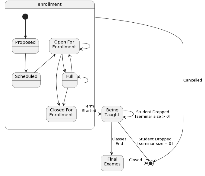
State Machine Diagram
An object responds differently to the same event depending on what state it is in. State Diagrams are typically used to depict the various states that an object may be in and the transitions between those states.
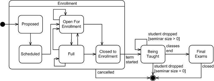
Let’s recreate this diagram using PlantUML:
@startumlstate enrollment {
  [*] --> Proposed
  Proposed --> Scheduled

  state "Open For\nEnrollment" as OpenForEnrollmentScheduled -up-> OpenForEnrollment
  OpenForEnrollment --> OpenForEnrollment
  OpenForEnrollment --> FullFull -up-> OpenForEnrollment
  Full -left-> Full

  state "Closed For\nEnrollment" as ClosedForEnrollment

  Full --> ClosedForEnrollment
  OpenForEnrollment -> ClosedForEnrollment
}state "Being\nTaught" as BeingTaughtClosedForEnrollment -right-> BeingTaught : Term\nStarted
BeingTaught -> BeingTaught : Student Dropped\n[seminar size > 0]state "Final\nExames" as FinalExamsBeingTaught --> FinalExams : Classes\nEnd
BeingTaught -> [*] : Student Dropped\n[seminar size = 0]FinalExams -> [*] : Closedenrollment -> [*] : Cancelled@enduml
The code above should result in a diagram like:
Component Diagram
A component diagram depicts how components are wired together to form larger components or software systems. They are used to illustrate the structure of arbitrarily complex systems.
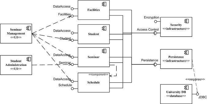
Let’s recreate this diagram using PlantUML:
@startuml
[Seminar\nManagement] <<UI>> as SeminarManagementUI
[Student\nAdministration] <<UI>> as StudentAdministrationUI[Facilities] as Facilities
[Schedule] <<Component>> as Schedule
[Seminar] as Seminar
[Student] as Student() "Facilities" as IFacilities
() "DataAccess" as IScheduleDataAccess
() "Student" as IStudent
() "DataAccess" as IStudentDataAccess
() "Seminar" as ISeminar
() "DataAccess" as ISeminarDataAccess
() "Schedule" as ISchedule
() "DataAccess" as IScheduleDataAccessDataAccess -- Facilities
IFacilities -- FacilitiesIStudentDataAccess -- Student
IStudent -- StudentISeminarDataAccess -- Seminar
ISeminar -- SeminarIScheduleDataAccess -- Schedule
ISchedule -- ScheduleSeminarManagementUI ..> IFacilities
SeminarManagementUI ..> IStudent
SeminarManagementUI ..> ISeminar
SeminarManagementUI ..> IScheduleStudentAdministrationUI ..> ISeminar
Seminar .left.> Schedule() "Encryption" as IEncryption
() "Access Control" as IAccessControl
() "Persistence" as IPersistence
() "JDBC" as IJdbc[Security] <<Infrastructure>> as SecurityInfrastructure
[Persistence] <<Infrastructure>> as PersistenceInfrastructure
[University DB] <<Database>> as UniversityDBIEncryption -- SecurityInfrastructure
IAccessControl -- SecurityInfrastructure
IPersistence -- PersistenceInfrastructure
IJdbc -- UniversityDBFacilities --( IAccessControl
Student --( IAccessControl
Seminar --( IAccessControl
Schedule --( IAccessControlFacilities --( IPersistence
Student --( IPersistence
Seminar --( IPersistence
Schedule --( IPersistenceIJdbc .right.> PersistenceInfrastructure  : <<requires>>@enduml
Conclusion
Looks good, doesn’t it? PlantUML forces me to use the standards of UML, it’s easier to design than dragging and dropping a lot of objects, it’s easier to maintain, and it’s nice to work with it. What else could I ask for?
Besides that, when used alongside Git, for example, we can even benefit from version control for our diagrams.
Give it a try, copy and paste one of the examples at: https://www.planttext.com and check the results by yourself.
I hope you have enjoyed this story. See you next time!
Contribute
Writing takes time and effort. I love writing and sharing knowledge, but I also have bills to pay. If you like my work, please, consider donating through Buy Me a Coffee: https://www.buymeacoffee.com/RaphaelDeLio
Or by sending me BitCoin: 1HjG7pmghg3Z8RATH4aiUWr156BGafJ6Zw
Follow Me on Social Media
Stay connected and dive deeper into the world of documentation with me! Follow my journey across all major social platforms for exclusive content, tips, and discussions.
